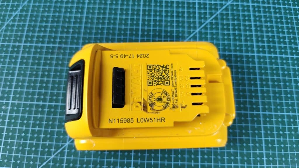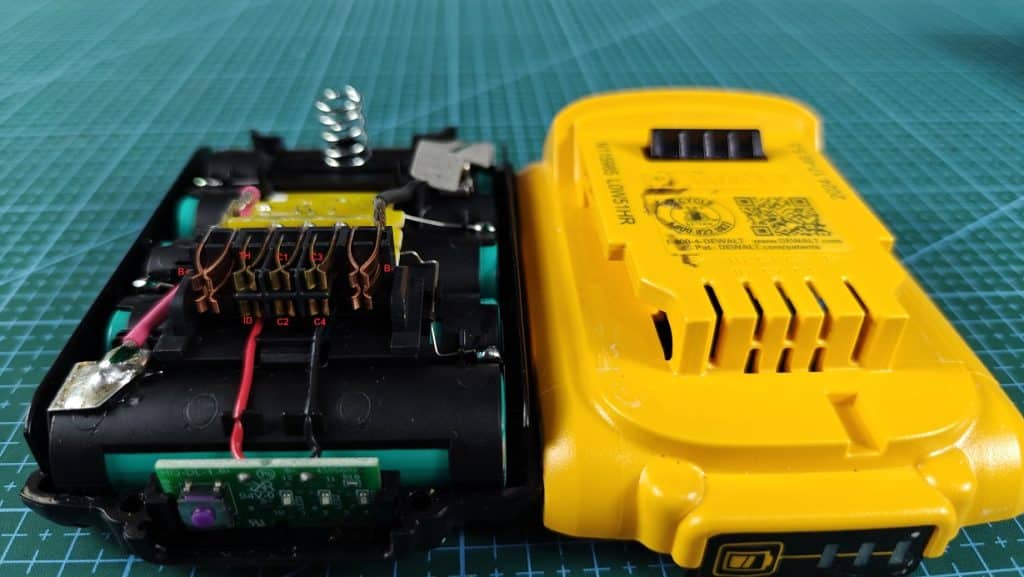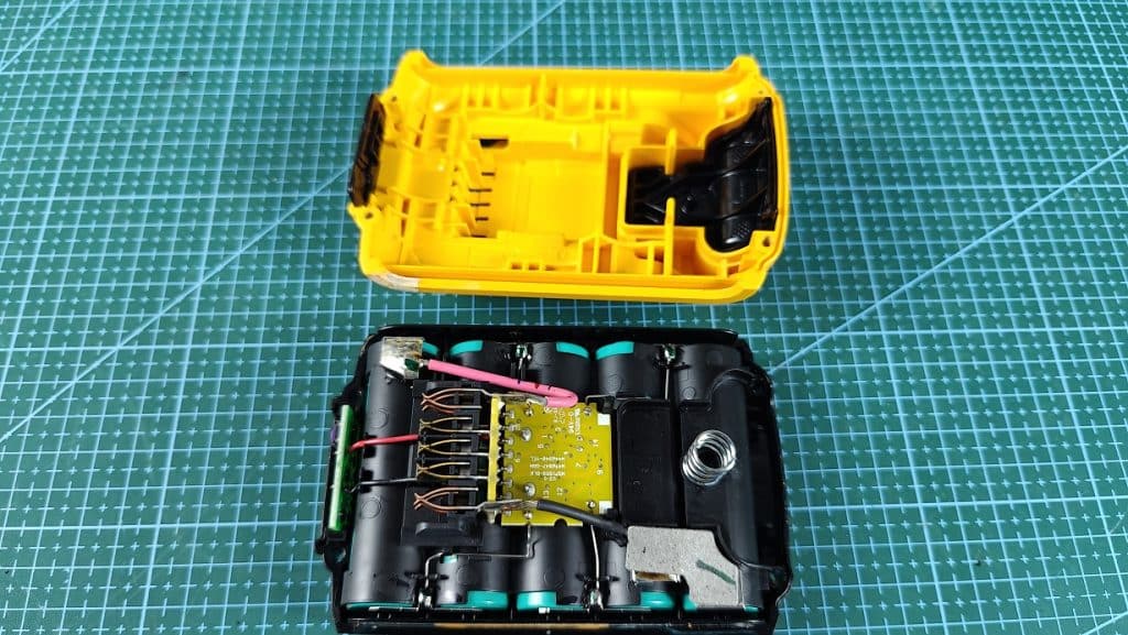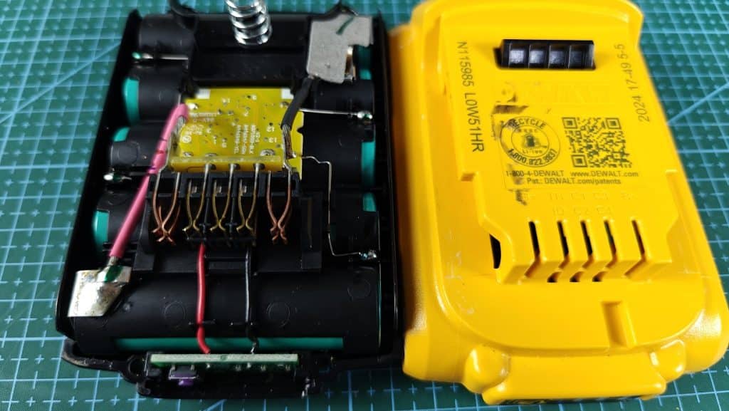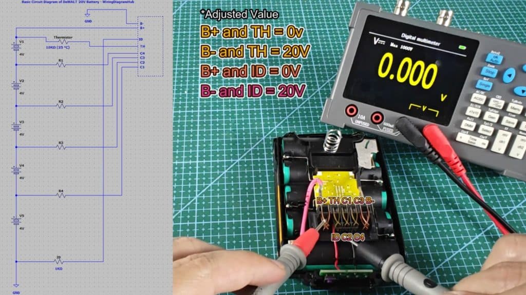
B– is Negative terminal
B+ is Positive terminal
ID is for tool to identify the battery
TH is Thermistor for temperature monitoring
C1 to C4 is junction between cell groups (for balancing)
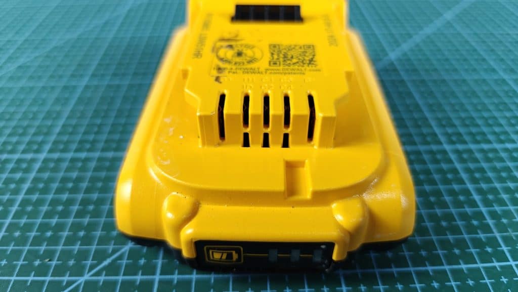
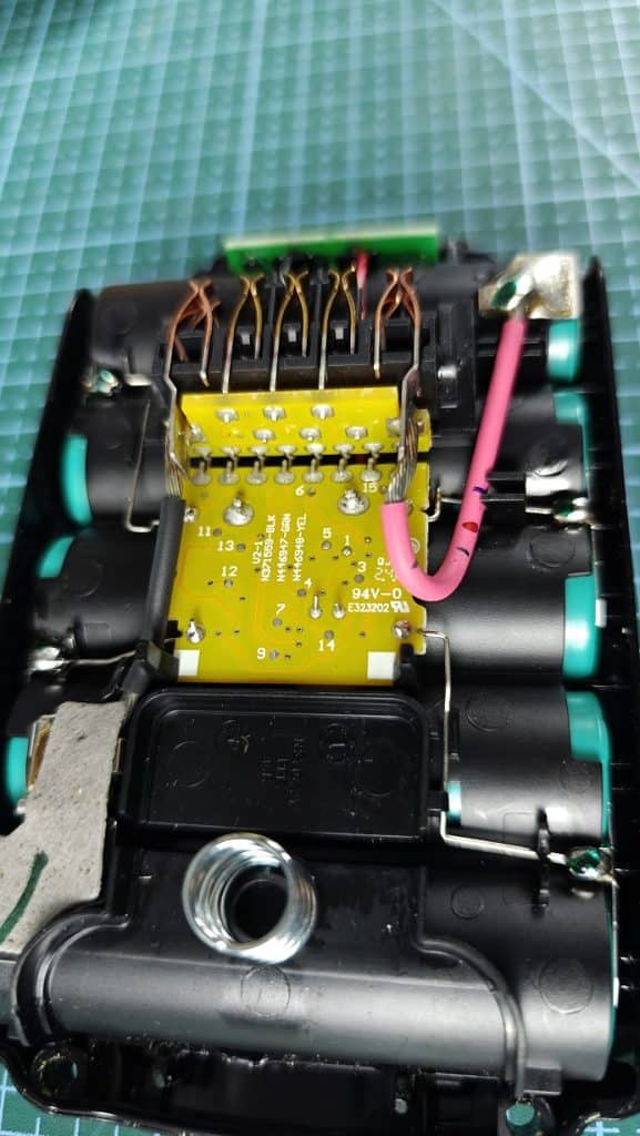
DeWALT 20V Battery Interface & Pinout Wiring Diagram
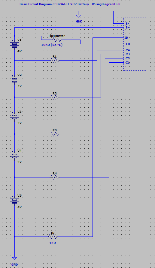
B+ and B- = 20v
B+ and TH = 0v
B- and TH = 20V
B+ and ID = 0V
B- and ID = 20V
B- and C1 = 4v
B- and C2 = 8V
B- and C3 = 12V
B- and C4 = 16V
B+ and TH = 10KΩ (25 °C), ~8KΩ (Current Temp)
B- and TH = 0Ω
B+ and ID = 0Ω
B- and ID = 1KΩ