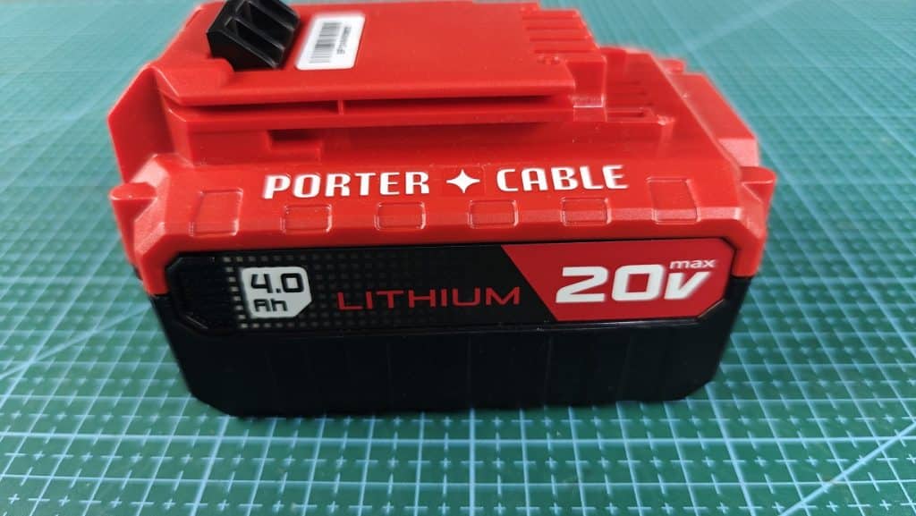
The Porter Cable tools mostly powered by a 20V Lithium Ion battery.
I own impact and drill manufactured by Porter cable, and also its 20V battery.
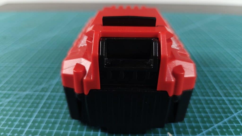
I removed the cover of the battery to check the pins inside.
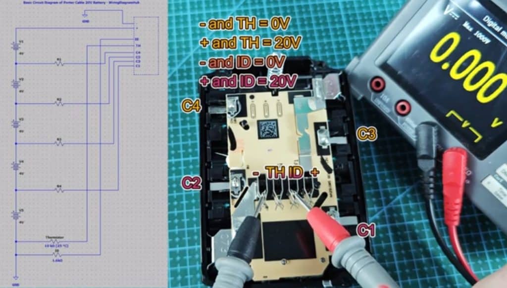
It has standard 4 pins which are as below.
– is Negative terminal
+ is Positive terminal
ID is for tool to identify the battery. The porter cable charger would read this ID pin to identify if this is original Porter Cable battery before start charging.
TH is Thermistor for temperature monitoring. This pin is common for tool battery, as most tool battery would not charge if the temperature is too hot or too cold.
C1 to C4 is junction between cell groups (for balancing). The porter cable has connected the cell in pack, and each junction is important to make sure every cell being charged balanced. So there won’t be a single cell that left behind and not getting charged.
Porter Cable 20V Battery Interface & Pinout Wiring Diagram
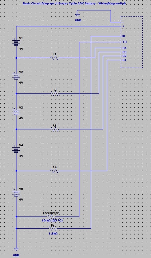
I spent some time to reverse engineer and draw the wiring diagram of this Porter Cable 20V battery.
Please take note this is the wiring diagram for 20V porter cable, if the battery you own is not 20V, its wiring diagram might not look like this.
– and + = 20V (Yes, as expected, when all cells are healthy, the voltage output is 20V)
– and TH = 0V
+ and TH = 20V
– and ID = 0V
+ and ID = 20V
– and C1 = 4v
– and C2 = 8V
– and C3 = 12V
– and C4 = 16V
– and TH = 10 kΩ (25 °C), ~8 kΩ (Current Temp). I believe the thermistor pin should read 10 kΩ at 25 °C as this is common for tool battery thermistor pin. When I measure the resistance of this pin, my room temperate is not exactly at 25 °C, that’s why I get around 8 kΩ. Thermistor resistance fluctuates based on the surrounding temperature.
+ and TH = 0Ω
– and ID = 1.6 kΩ (Charger read this to confirm it is indeed an original porter cable 20v battery, otherwise it won’t start charging)
+ and ID = 0Ω
So, it says 20V maximum, unless there is some short circuit or faulty inside, its output voltage should not exceed 20V.
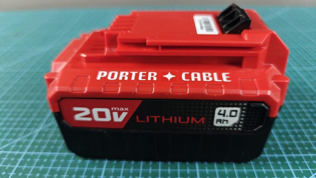
This is a 4.0aH porter cable battery, hence it would have 2 rows of battery, each row consists of 5 pieces of 18650 battery cells.
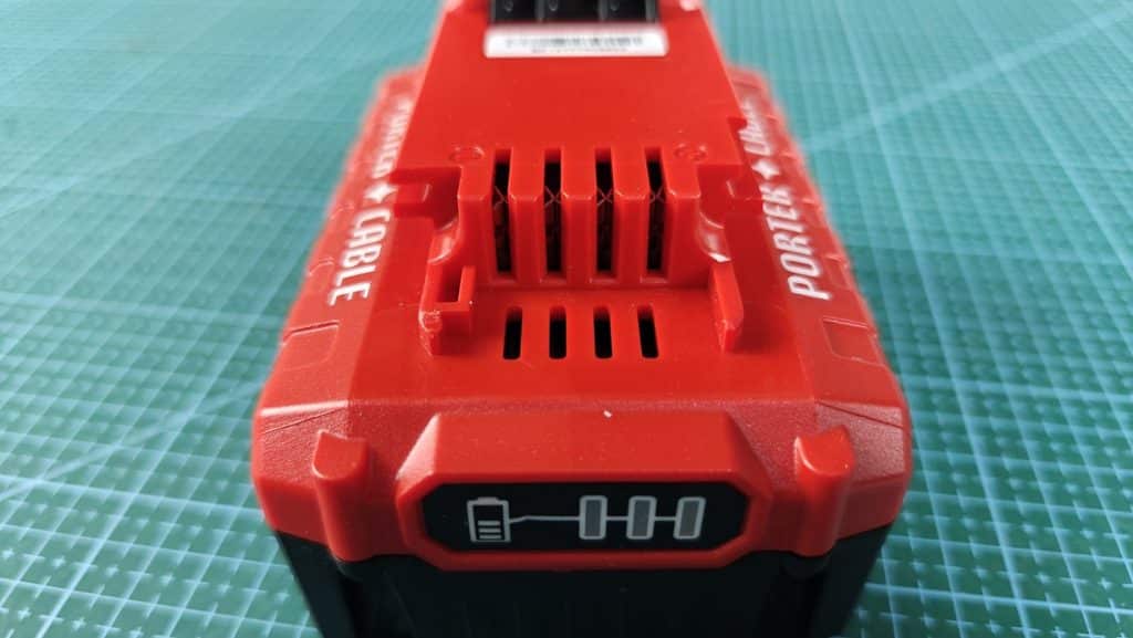
The porter cable 20V only mark the positive and negative pins clearly.
They did not label the center pins, but from my observations, those middle pins are thermistor and ID pin respectively as I explained before.
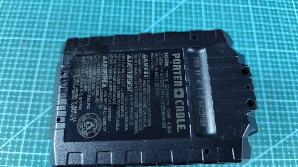
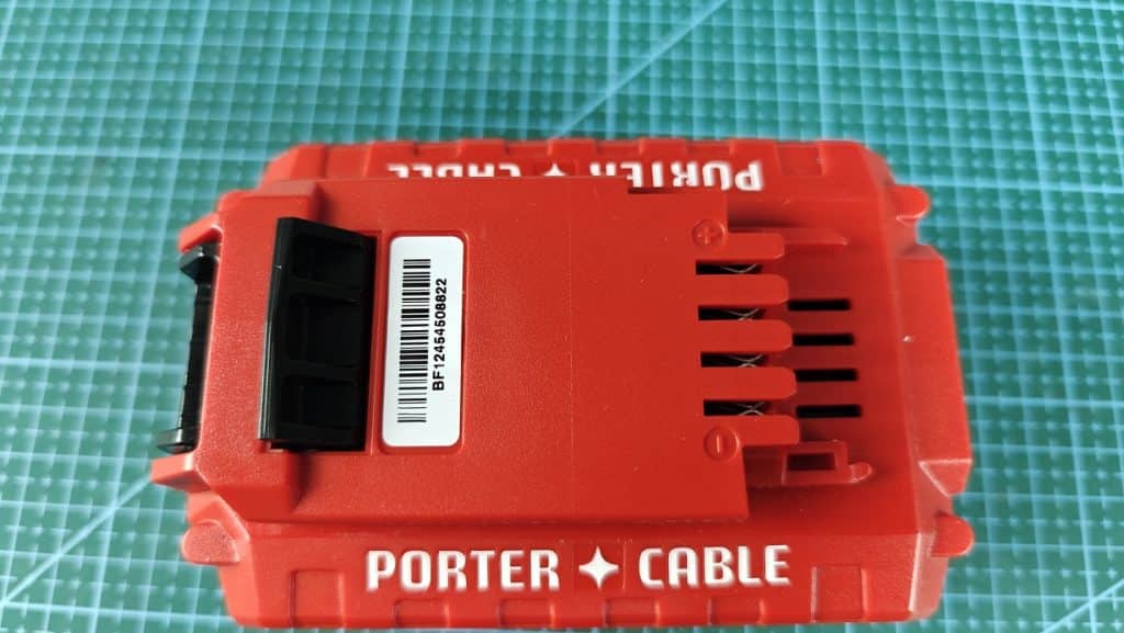
The model of this battery is PCC685L, your battery might not be the exact same model as mine.
But overall its internal components should look quite similar as shown in the image below:
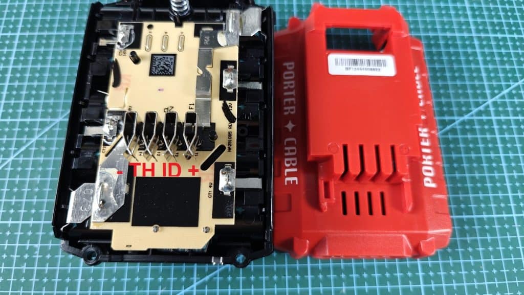
I labeled the Pins, namely -, TH, ID and + clearly, and compare it with the casing side by side.
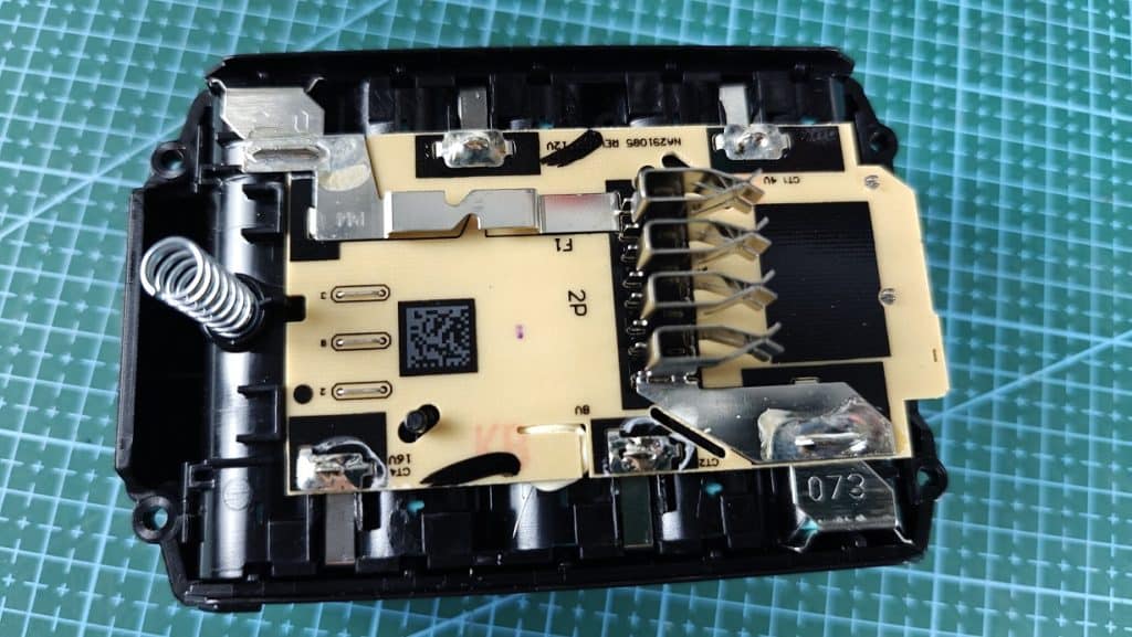
If you would like to know more about the this specific porter cable battery, they even included a QR code on the board.
Simply scan the QR code to know more information about this porter cable battery.
You could see the “073” marking as shown in the image above, it is actually the manufacturing or batch code.
This could be useful for the factory internal tracking.