The Ryobi 18V battery is the most common ryobi battery on the market today. I own few of them and not all of them work correctly.
Some might blink green and red light and not charging.
I tried to reverse engineer the Ryobi 18V battery and draw the pinout diagram.
Here are the terminals on the Ryobi 18V battery, check for the labels on the battery.
– is Negative terminal
+ is Positive terminal
T1 is Thermistor, mostly used in tool battery for temperature monitoring. If temperature of the battery is too hot or too cold, the charger or ryobi tool would read the resistance value and decide if the battery is fit to be used.
C1 to C4 is junction between cell groups, it does not have official label on the battery itself, but I marked them down.
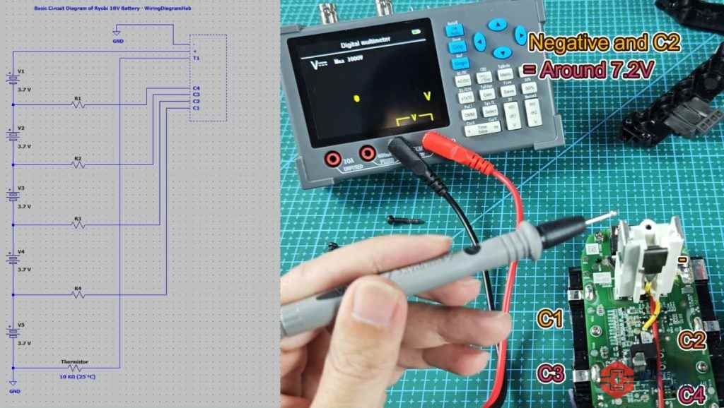
Also, I recorded a video for this Ryobi 18V battery wiring diagram, tested the voltage for most terminals, and measured the resistance.
Ryobi 18V Battery Interface & Pinout Wiring Diagram
As shown in the wiring diagram below, this is the pinout diagram of the Ryobi 18V battery.
It was build using 18650 battery cells, connected in series to provide total voltage output of 18V.
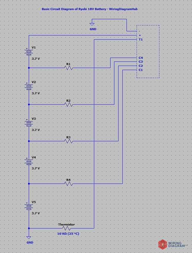
– and + = 18V (As mentioned above, 3.7V x 5 ~ 18V)
– and T1 = 0V
– and C1 = 3.7v (Voltage between cells, for one cell only)
– and C2 = 7.2V (Two cells)
– and C3 = 11.1V (Three cells)
– and C4 = 14.8V (Four cells)
– and T1 = 10 kΩ (25 °C), ~8 kΩ (Current Temp). When I measured the resistance value of the thermistor, it shows around 8 kΩ at my room temperature that time. I believe it use an industry standard thermistor that shows 10 kΩ at 25 °C.
+ and T1 = 0Ω
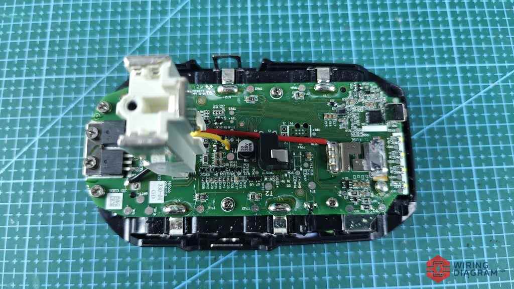
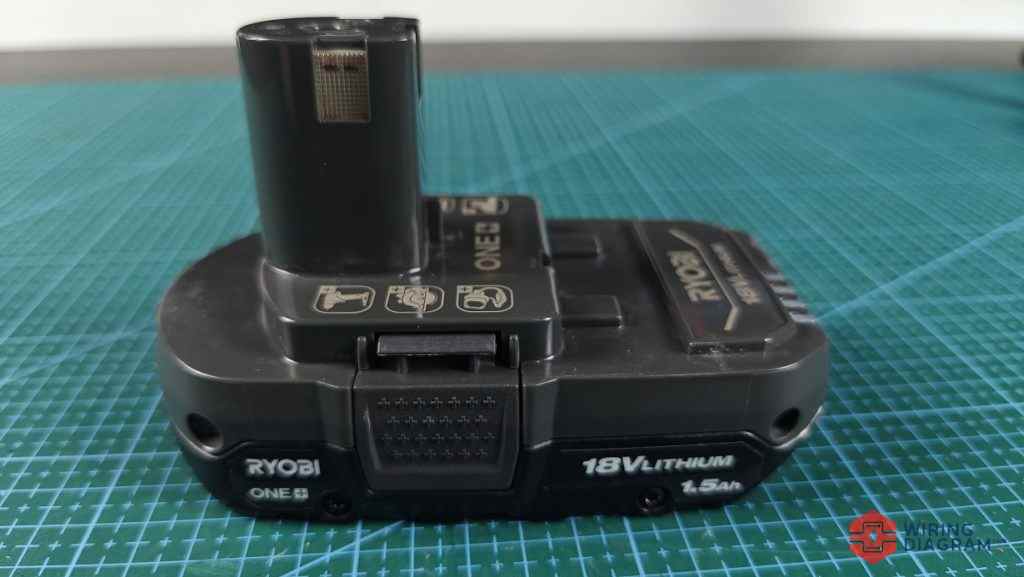
As shown in the image above, this is the top view of the Ryobi 18V battery .
The battery PCB or battery management system consists of various electronic components.
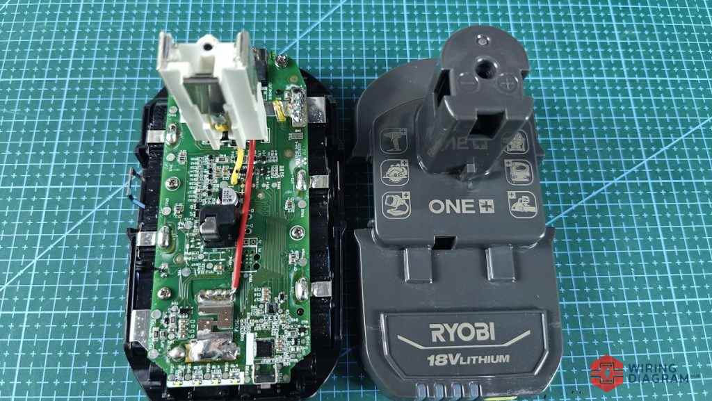
Besides, I removed the cover of the Ryobi 18V battery, and put them side by side so that you can clearly see the terminal, Positive, Negative and Thermistor.
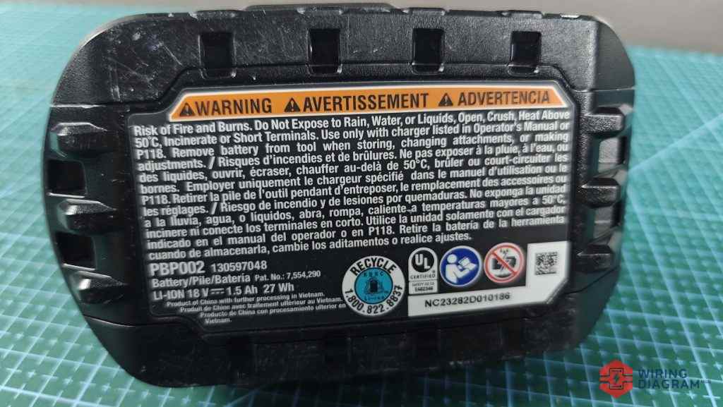
At the bottom of the ryobi 18v battery are some of the warning message, yes this battery could not be exposed to rain or fire.
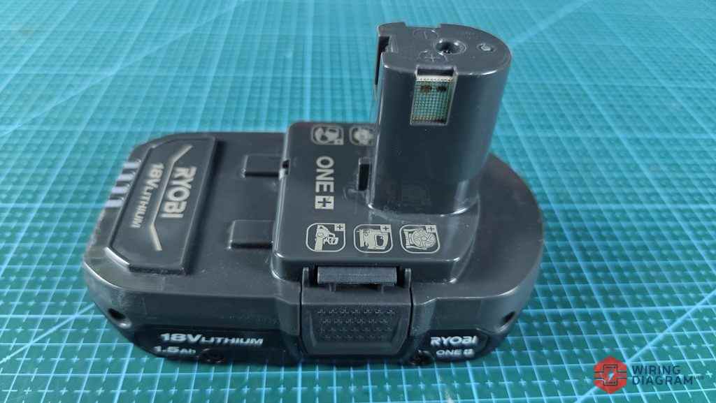
The shape of this Ryobi 18V battery is somewhat unique. It likes a “Joystick”.
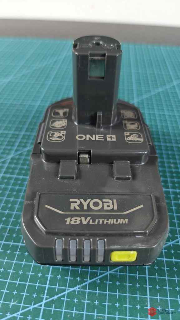
The front of the battery are 4 LEDS that indicate the current level of the battery.
If only 1 LED left or none at all, charge the battery.
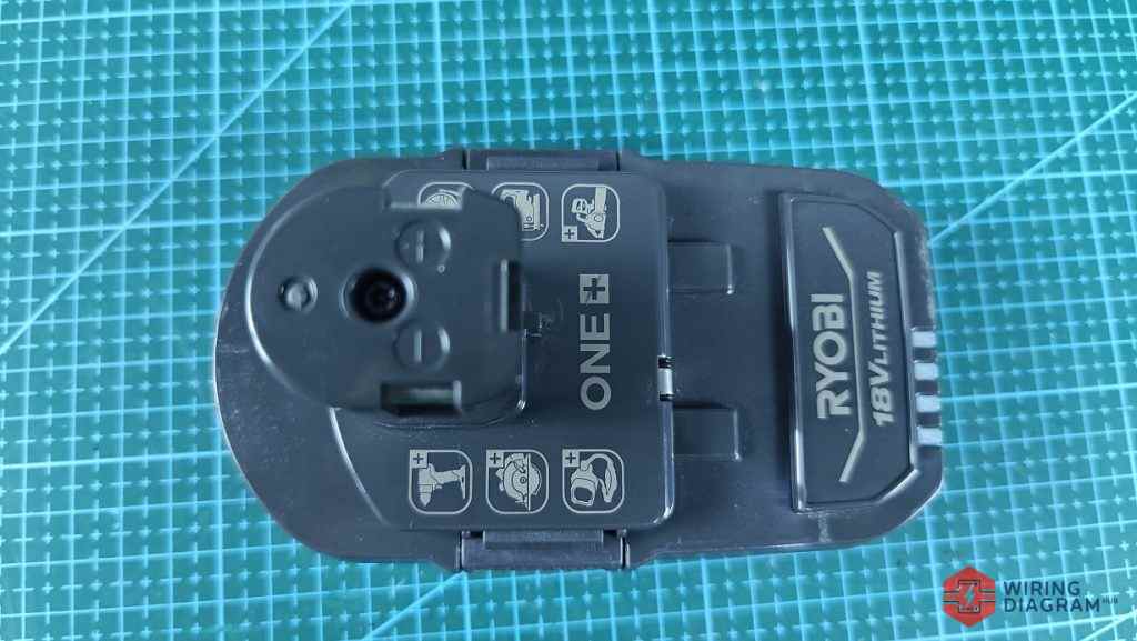
To remove the battery cover, first you have to remove the screw as shown in the image above.
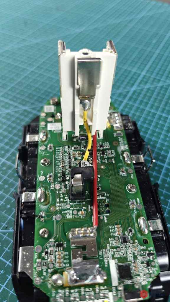
This is the close view of the Ryobi battery PCB.
If your Ryobi 18V battery is not working, not charging or have any problem, it could be due to either bad 18650 battery cells, or the electronic components are burnt on this board.