I own a 18V bosch battery and I want to know how is its internal mechanism works,
Hence, I removed the battery cover and measured the voltage across different terminals, and also measure the resistance across some terminal.
In short, the bosch 18V battery has these pins, namely:
– is Negative terminal
+ is Positive terminal
tool is for tool to identify the battery, I believe the bosch tool would read this pin to decide if the battery connected is compatible or not
NTC is Thermistor, commonly used in tool battery to monitor the temperature of the battery
charger – just similar to the tool above, for charger to read and identify the bosch before start charging
C1 to C4 is junction between cell groups, each cells must be charged in balance
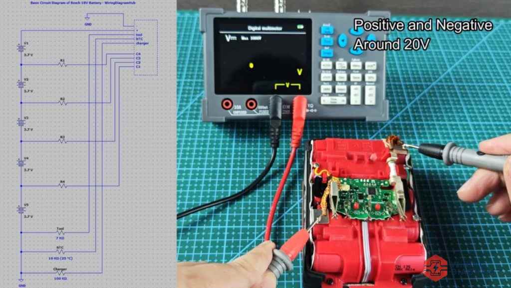
I also made a video show the voltage and resistance across the bosch 18v battery.
Bosch 18V Battery Interface & Pinout Wiring Diagram
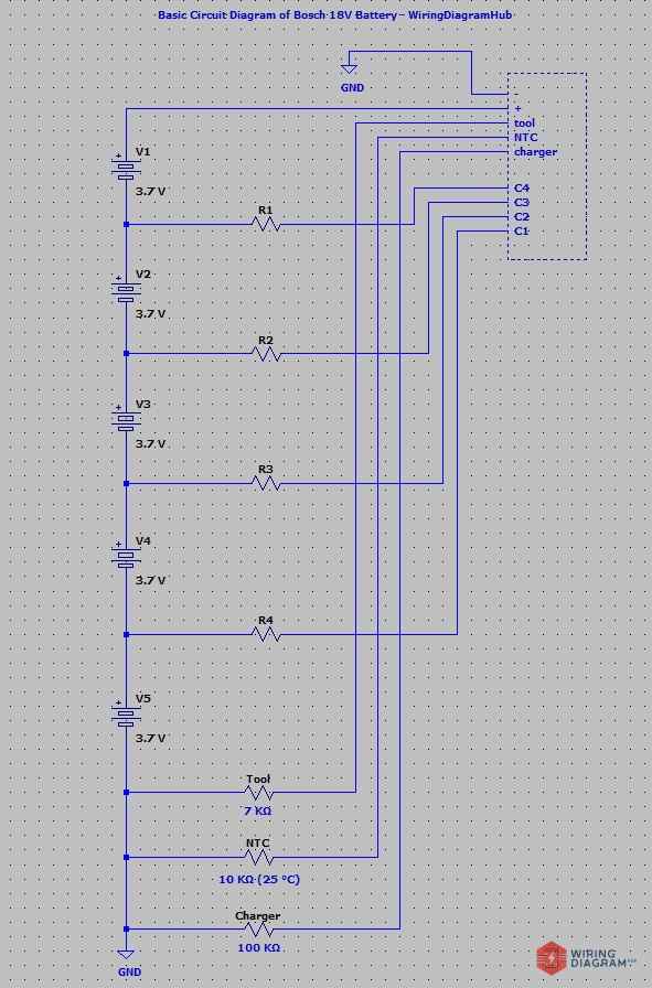
The pinout diagram of the bosch 18v battery above is made by me, this is a basic wiring diagram that I reverse engineer the bosch 18v battery.
Below shows the voltage and resistance value that I got across this process.
– and + = 18V
– and tool = 0V
+ and tool = 18V
– and ntc = 0V
+ and ntc = 18V
– and charger = 0V
+ and charger = 18V
– and C1 = 3.7v (one cell)
– and C2 = 7.2V (two cells)
– and C3 = 11.1V (three cells)
– and C4 = 14.8V (four cells)
– and tool = ~7 KΩ – The bosch tool should read this value, if any resistor value is much lower or higher than this value, the tool would think it is not an original bosch battery, or not a compatible one
+ and tool = 0 Ω
– and NTC = 10 KΩ (25 °C), 4.6MΩ likely measuring across protection circuitry, not directly across the NTC. Yes, this is a bit weird as most tool NTC that give 10 KΩ at 25 °Cm but I measured 4.6MΩ for this one. It is mostly likely the measurement is done directly to the NTC, but there is other circuitry as well.
+ and NTC = 0 Ω
– and charger = ~ 100 KΩ – Just like the tool above, the bosch charger would read this pin, if any value is lower or much higher than this resistance value, the charger would think it is not a compatible one and refuse to charge.
+ and charger = 0 Ω
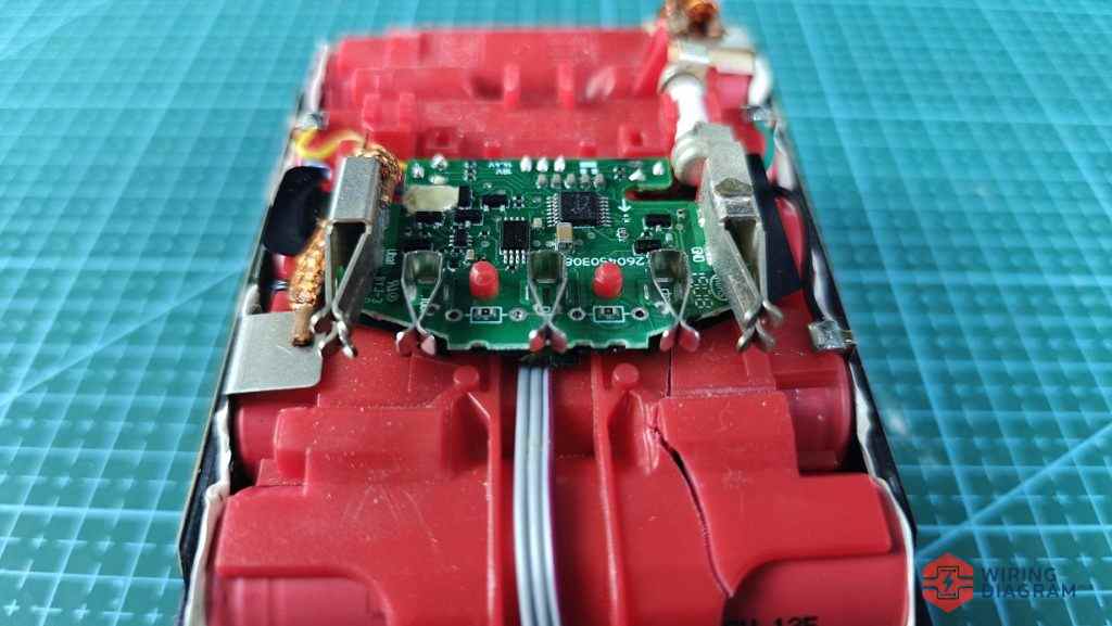
The image above show the Battery management system of the bosch 18V battery.
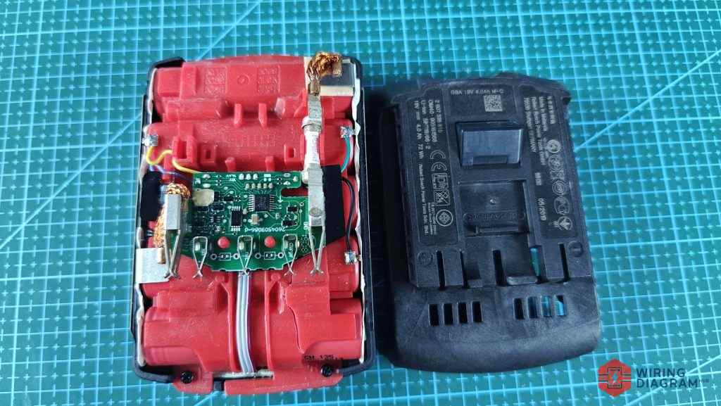
I removed the battery cover and put them side by side so that easier for you to see the pins clearly.
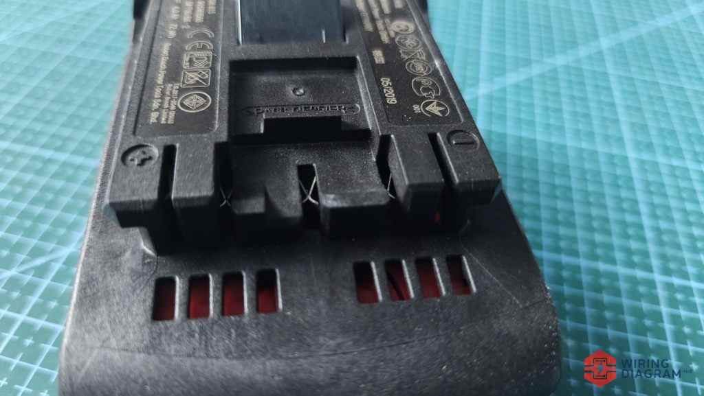
Here’s the close view of the bosch 18v battery’s pins, it has positive, negative, tool, charger and NTC.
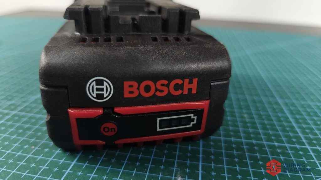
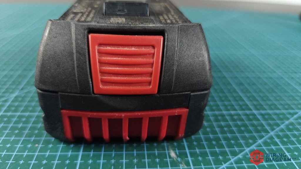
Yes, it also contain the battery level indicator where you can press it to check the current battery level.
If it is too low, you might need to charge it.
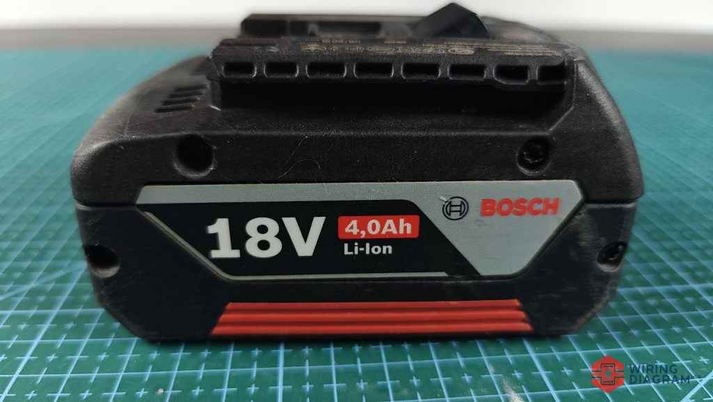
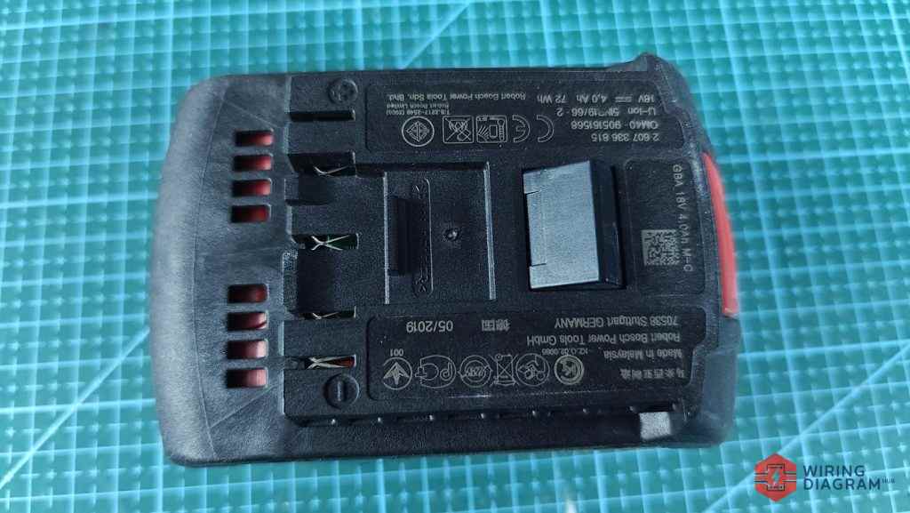
Mine is a 4.0Ah bosch 18v battery as shown in the image above.
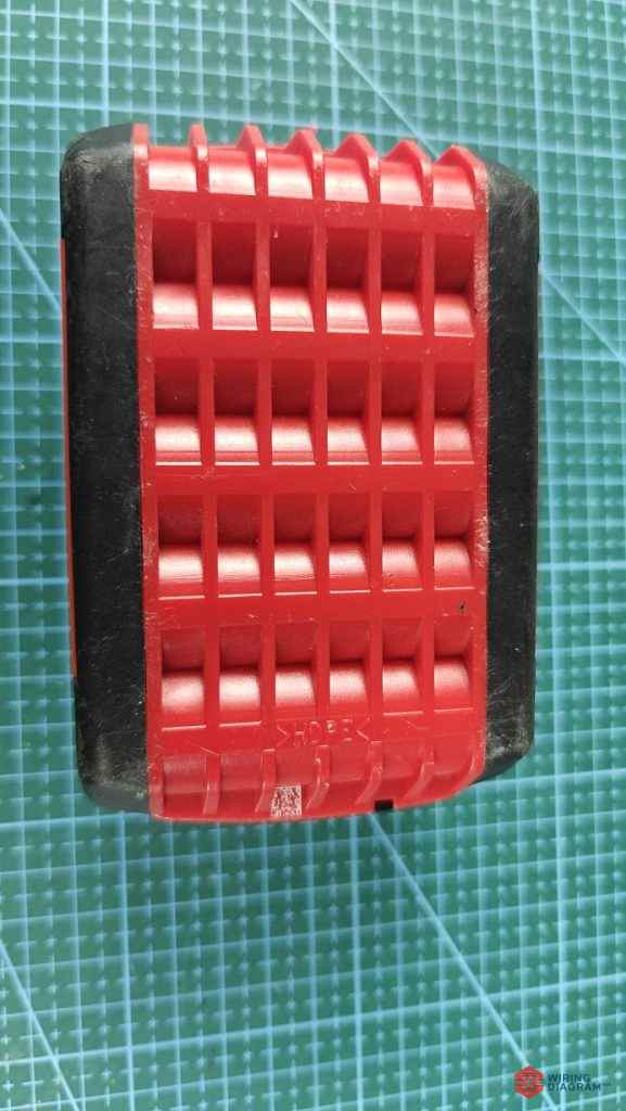
On the other hand, the image below show the top view of my bosch 18V battery.