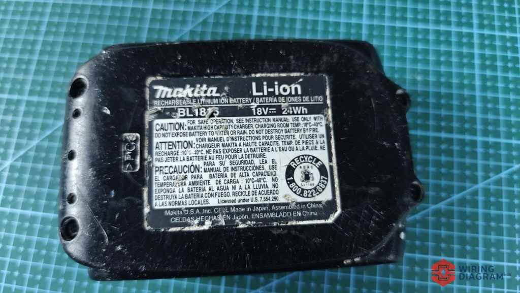
The makita 18v battery is one of the most commonly used battery in their tool battery series.
Compared to its 12V and 40V battery series, the 18v is more common and widely used.
I own multiple Makita 18V battery and I decided to open the cover of one of those to check the voltage and resistance across the pins the terminals.
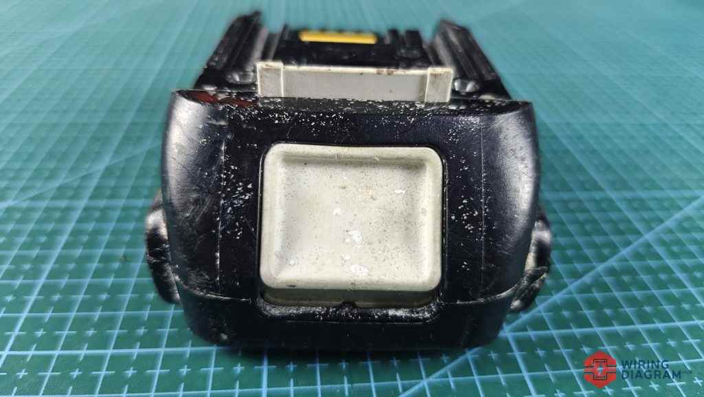
In short, the 18V makita battery interface contains:
– is Negative terminal
+ is Positive terminal
TH is Thermistor, mostly NTC to monitor the temperature before decide if the battery can be used or charged
C1 is junction between cell groups, it only has one clearly visible junction, unlike other tool battery like the dewalt 20v battery
Pin 1 to 7 is for makita tool or charger to identify the type of makita battery being used or charged
I made a video showing how I measured the voltage and resistance across the pins and terminal.
Makita 18V Battery Interface & Pinout Wiring Diagram
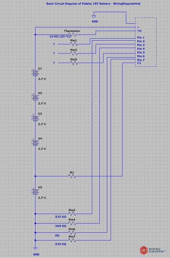
I used a software to draw the wiring and pinout of the Makita 18v battery as above.
It is not perfect but this is the best I can reverse engineer for now.
From the diagram above, you can see that I am unable to decide how the Pin 1, 3 and 5 are connected to battery management system.
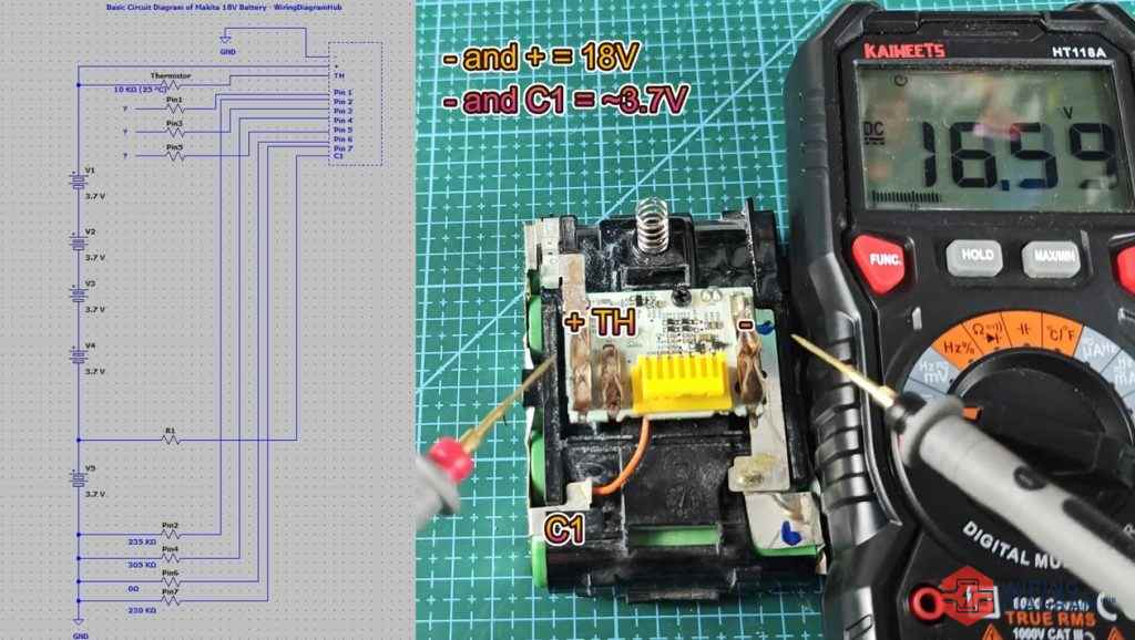
However, I was able to draw the basic wiring diagram of the makita 18v battery based on the data I have below:
– and + = 18V
– and C1 = ~3.7V, only one cell
+ and Pin 1 = 0V
+ and Pin 2 = 18V
+ and Pin 3 = 0V
+ and Pin 4 = 18V
+ and Pin 5 = 0V
+ and Pin 6 = 18V
+ and Pin 7 = 18V
– and Pin 1 = 18V
– and Pin 2 = 0V
– and Pin 3 = 18V
– and Pin 4 = 0V
– and Pin 5 = 18V
– and Pin 6 = 0V
– and Pin 7 = 0V
– or + and TH = should be 10 KΩ (25 °C) – In the video above, you can see the resistance value I got is nearly zero.
Why read ~0 Ω?
TH is tied to pack negative (or positive) in the Makita design. Some manufacturers route the thermistor (TH) return to the pack common (often NEG). If the TH terminal is a direct connection or shorted to that return on the pack PCB, a multimeter will read ~0 Ω.
+ and Pin 1 to 7 = 0 Ω
– and Pin 2 = ~235 KΩ – not sure if makita or charger use this pin for what purpose
– and Pin 4 = ~305 KΩ – also not sure
– and Pin 7 = ~230 KΩ – also not sure
– and Pin 1, 3, 5, 6 = 0 KΩ
TH and Pin 1 to 7 = 0Ω
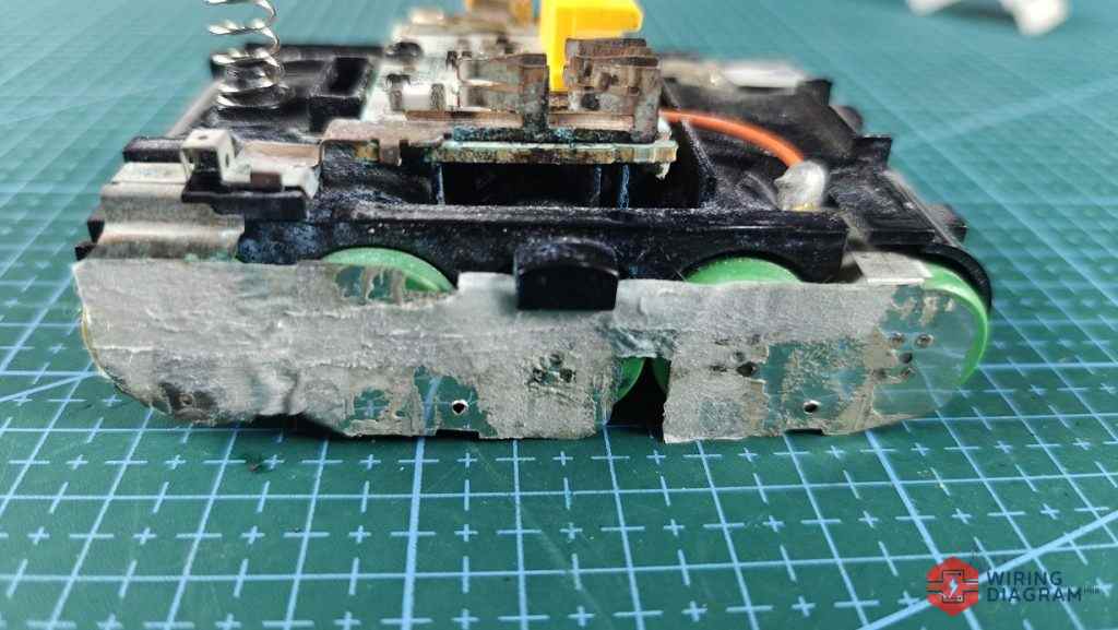
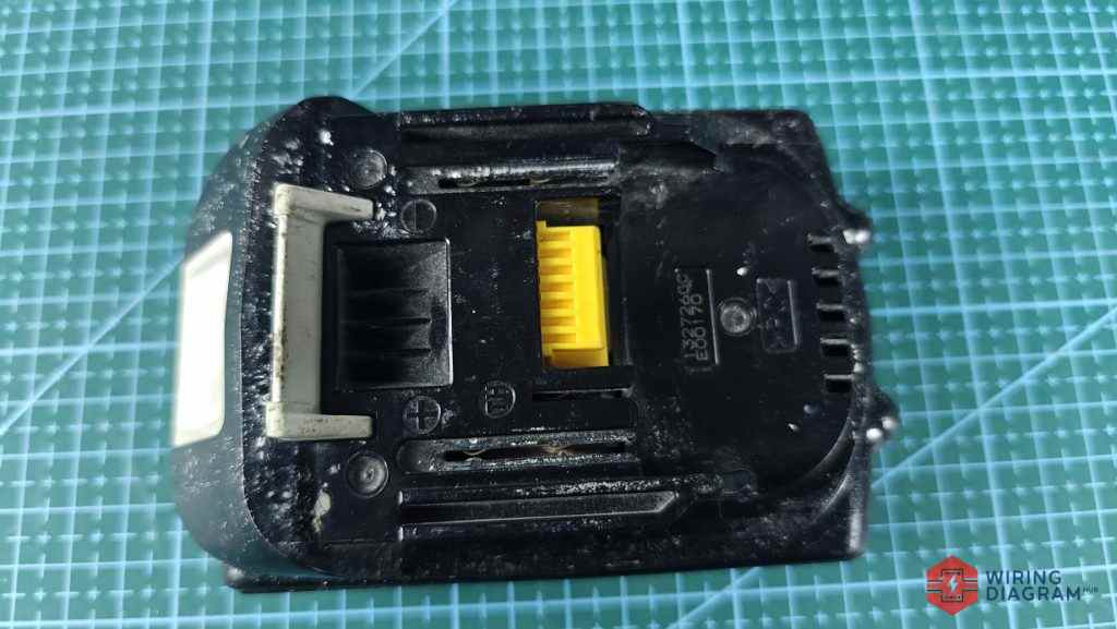
As you can see from the image below, this low Ah makita battery is built using 5 pieces of 18650 battery connected in series to give total output voltage of 18V.
Normally if you Makita battery is not charging, or it lost charge fast, you would need to identify the bad battery cell and replace it.
Then the entire battery pack would work again.
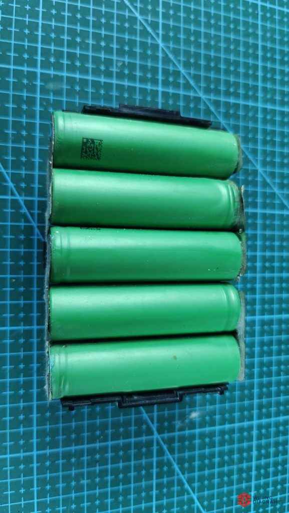
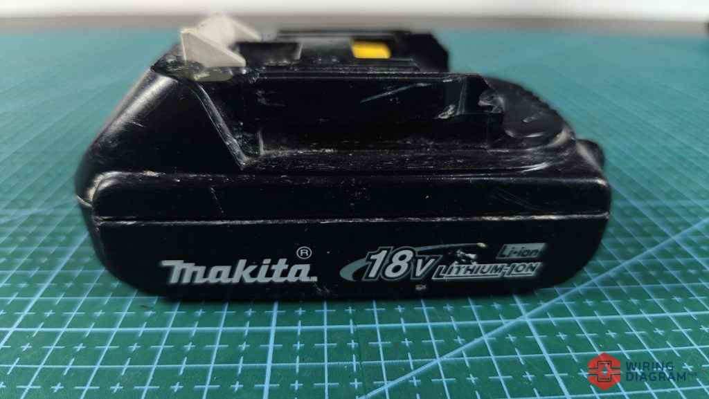
Here is the side view of the Makita 18V battery.
The connection between the battery cells are done using spot welding technique I believe.
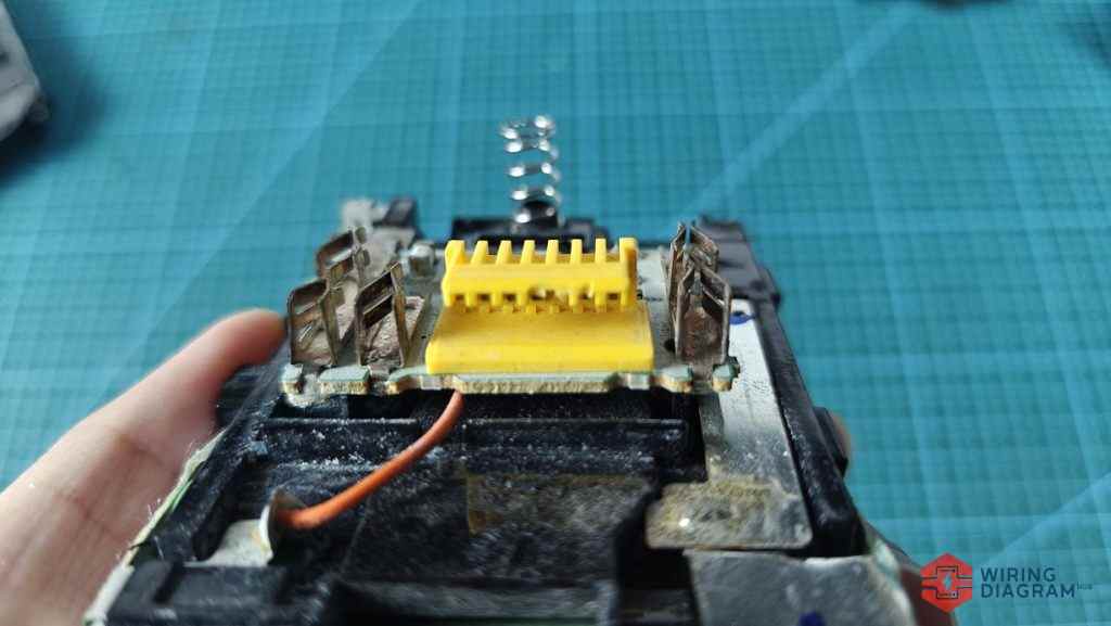
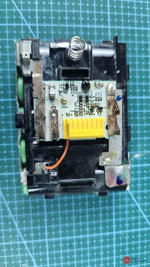
The battery management system of the Makita 18V battery.
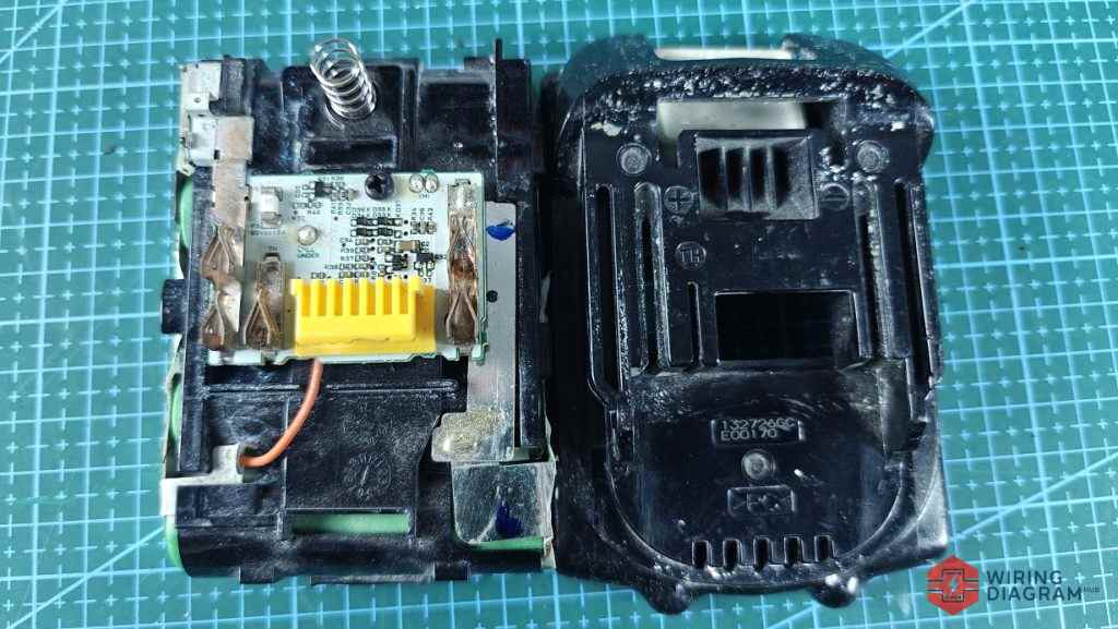
I removed the cover of the battery and put them side by side side so that you can easily check the position of the pins and their label.
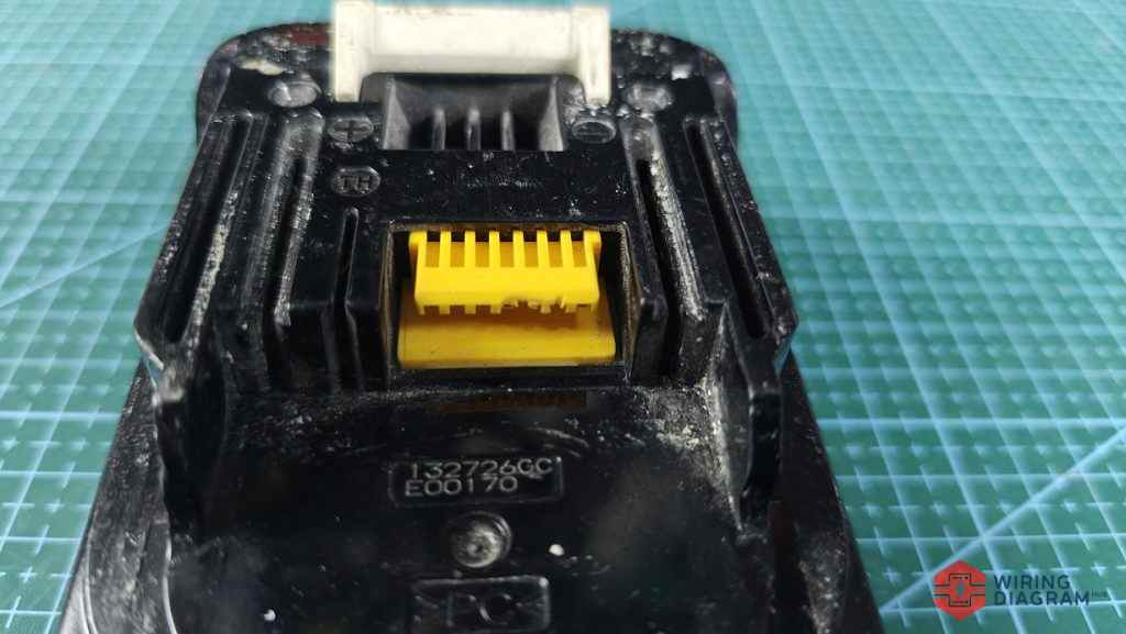
As shown in the image above, the yellow section contain 7 pins, which I labeled pin 1 – 7 above.
Some pins show resistance value when being measured, while some not.
Although I am not particularly sure what’s the purpose of each pin, but I believe it is for the makita tool or charger to read these pins to identify the type of makita battery being connected.
As you can see from the image above, the makita 18v battery has more pins compared to other tool battery.
It is also more complicated and harder to reverse engineer.