I own both Hart 20V and 40V battery and I would say the 40V battery is a massive one compared to its 20V.
I already draw the pinout diagram of the 20V, now I would construct the wiring diagram for the Hart 40V battery too.
As you can from the image above, or from the battery itself, it consists of the following terminals.
– is Negative terminal
+ is Positive terminal
ID – I think this is a resistor, when connected to Hart tool or Hart 40V charger, they would read this pin to confirm the identity of the battery.
D – Normally represent “Data”, for communication purpose between Hart tool, charger and Hart 40V battery
TH – Represent Thermistor, this is type of resistor that its resistance value changes with temperature.
C1 to C9 are not officially marked on the Hart 40V battery itself, I marked them on the image, those are the junction between cells, normally purpose is to charge all the battery cells in balance.
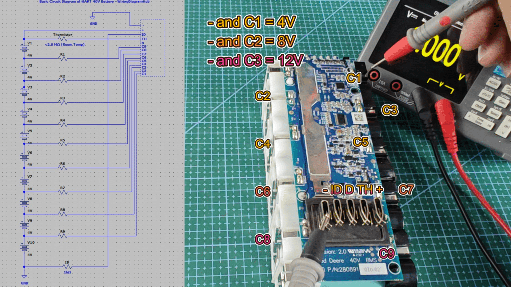
I recorded video above to demo how I measured the voltage between the terminals, and also the resistance value across the pins.
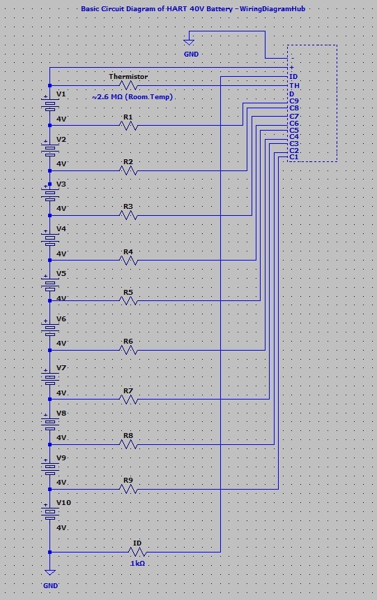
HART 40V Battery Interface & Pinout Wiring Diagram
After reverse engineering, I managed to draw the pinout diagram of this Hart 40V battery.
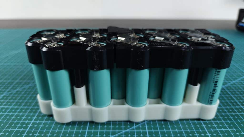
It consists at least 10 piece of 18650 battery cells in series, to output the total voltage of 40V.
If your Hart 40V battery has high Ah, it might even have more battery cells, like 20, 30, etc.
Data Measured from HART 40V Battery
Here are the data I managed to record.
Positive and Negative = 40V (If all battery cells are healthy, the voltage between positive and negative terminal should be around 40V)
– and ID = 0V
+ and ID = 40V
– and D = ~ 2.8V (Look likes the Data pin is connected between positive and negative terminal)
+ and D = ~ 3.6V
– and TH = 40V
+ and TH = 0V (I made a mistake in the video above, the voltage between + and TH should be zero, not 40V)
– and C1 = 4V (Voltage measured between negative and one cell)
– and C2 = 8V (Two cells)
– and C3 = 12V (Three cells)
– and C4 = 16V (Four cells)
– and C5 = 20V (Five cells)
– and C6 = 24V (Six cells)
– and C7 = 28V (Seven cells)
– and C8 = 32V (Eight cells)
– and C9 = 36V (Nine cells)
– and ID = ~ 1 kΩ (the Hart 40V tool or the charger would read this pin to identify is the connected battery is an original Hart battery, the resistance value they could accept would be around 1 kΩ)
+ and ID = 0 Ω
– and D = 0 Ω
+ and D = 0 Ω
– and TH = 0 Ω (Room Temp)
+ and TH = ~ 2.6 MΩ (Room Temp) (I think it is still using a common NTC that give 10 kΩ at 25 °C. The high resistance value measured could be due to the TH pin is connected to other circuit, or hide behind the other complex circuity)
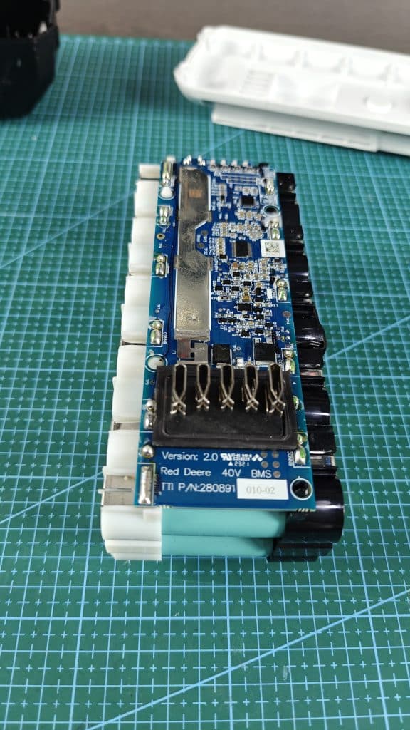
The model of Hart 40V battery I own is HLBP02, which is 4Ah 40 battery.
Another common 40V Hart battery is 2Ah, which is much smaller in size and consists only 10 pieces of 18650 battery cells.
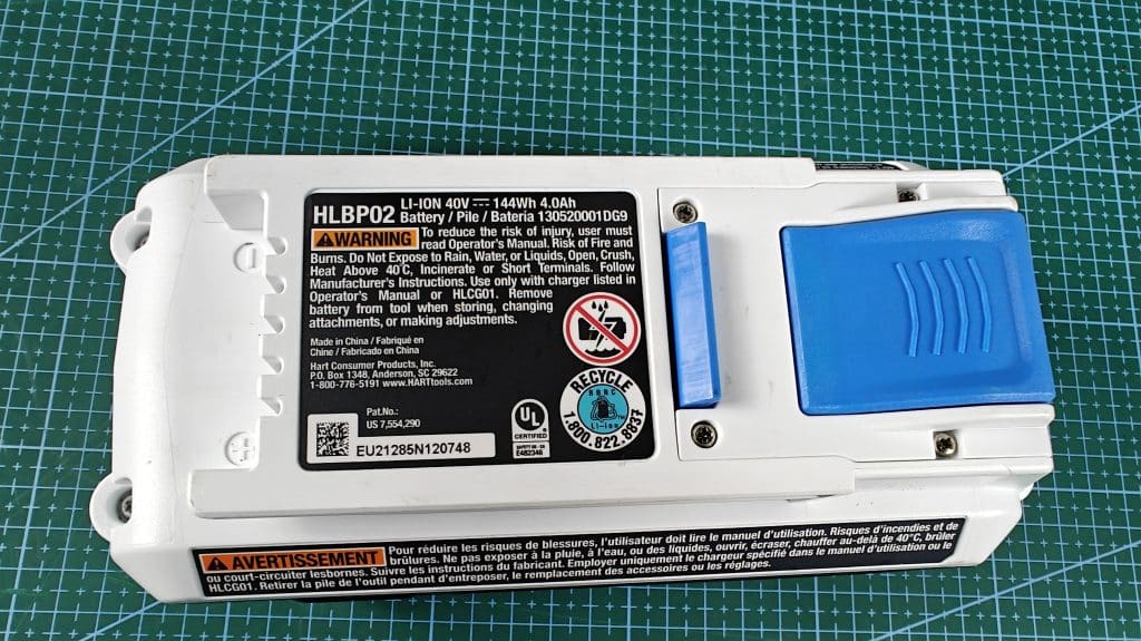
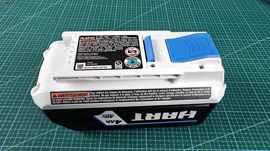
The top view of the Hart 40V battery, consists of warning message that it should not be exposed to fire or rain.
Also some information like LI-ION, 40V, 144Wh and 4.0Ah.
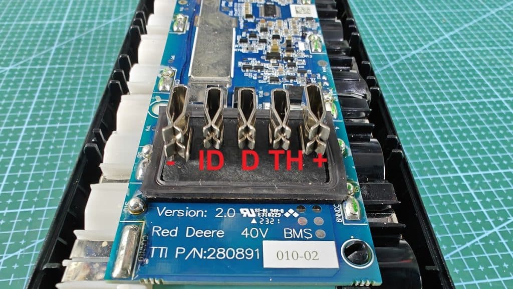
The is the close view of the five pins, the left is the negative terminal while the right is the positive terminal.
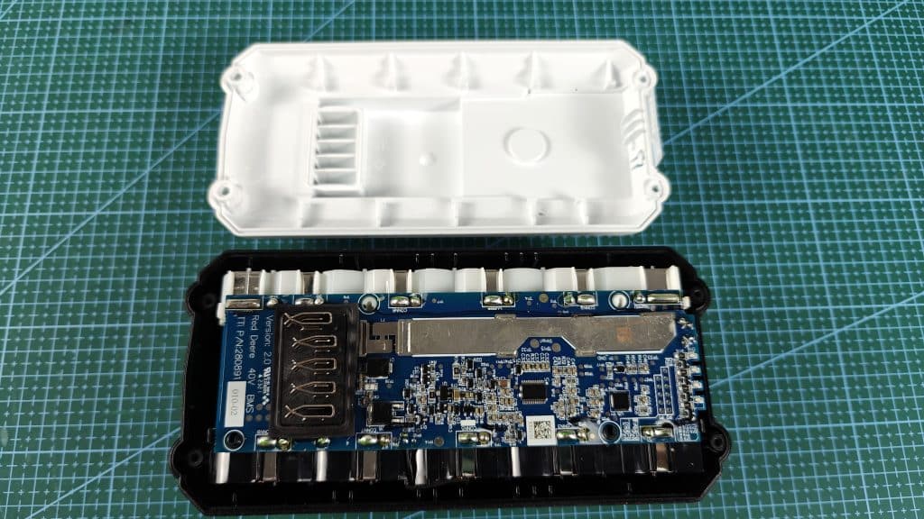
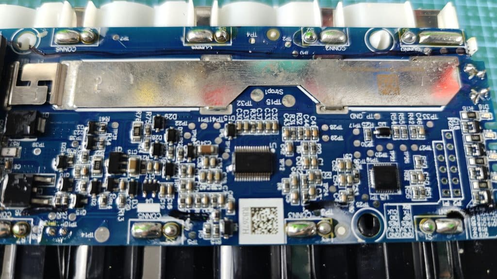
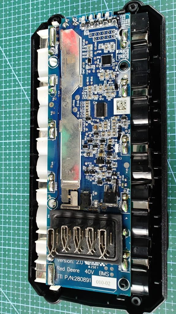
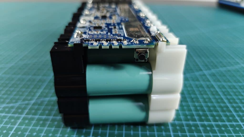
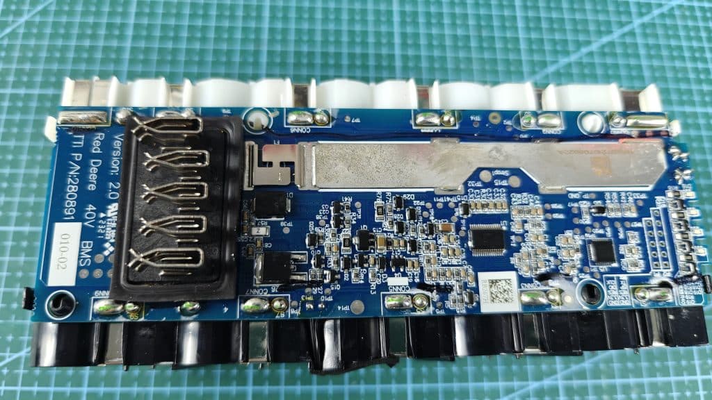
I removed the cover of the battery and you can clearly see the battery management system of this HART 40v battery.
The image below show the five pins I labelled in red, namely -, ID, D, TH and +
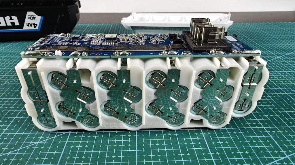
As you can see from here, mine is a 4Ah capacity battery, and it consists of 20 pieces of 18650 battery, each 10 pieces connected in series, then the battery pack connected in parallel to give the total output of 40V, and 144Wh, or 4.0Ah capacity.
There is a small button at the front of the battery, this is the battery level indicator.
Press it and the LEDs would show the current level of the battery.
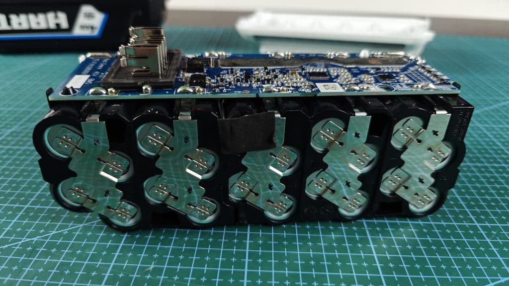
The bottom view of the 18650 battery cells for this battery pack.
This is quite a complex circuity if you do not have the exact wiring diagram to refer.
Hence, I was only able to construct the basic version of the pinout diagram of this Hart 40V battery.